 |
||||
| We Wrote the Book on Moldable Low-Friction Bearing Materials
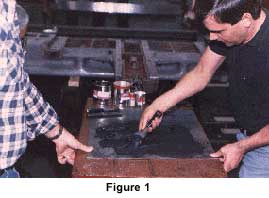
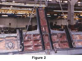
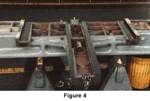
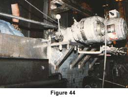
Replication techniques dramatically reduce the time and cost associated with maintaining or rebuilding machine tools by fundamentally changing the rebuilding process. Being epoxy-based, their application advantages. Replication materials can be molded to fit virtually any slide surface including box ways, dove tails, vee ways, round ways, quills, screws, etc. One surface, replicates that accurate surface onto the mating component while that component is in its correct alignment. This procedure eliminates the need for many precision machining or scraping operations. It also makes in-field repair and rebuilding of machine tools more practical. Replication techniques were originally developed in Europe during the 1960's for the assembly of new machines. These techniques are now used frequently in the United States machine tool industry. There are two main types of replication materials: 1). Materials meant for fitting static components. For instance, fitting ball screw bearing housings parallel to guide ways, and 2). Materials meant to produce sliding or dynamic surfaces, such as mating a lathe saddle square to the bed ways. The formulations of the dynamic materials are more critical due to more demanding technical requirements. Dynamic materials require low coefficients-of-friction, high wear properties, low abrasion rates and greater resistance to chemicals and coolants. Both static and dynamic materials come in fluid or putty consistencies. The different consistencies exist mainly for ease of application. When components are difficult to align or time consuming to check, it would be recommended to align, seal and inject a fluid type material. Where alignments are easier to repeat and check, the putty material would be recommended. It is not necessary to provide injection ports or sealing when using putty. The rebuilding of standard ways is the most common use for replication materials. Application photos taken in the rebuilding department of Pratt and Whitney Machine Tool Corp., West Hartford, CT, shows clearly the use of both Moglice (Moglice is a popular brand name in replication materials) putty and fluid materials. Figure 1 shows putty material being mixed on a piece of sheet metal. In figure 2 the putty has been trowelled onto the adhesion surfaces of a jig bore saddle, in figure 3 the saddle has been set on the base at its original elevation and the alignment checked. The next day the excess putty is trimmed off the finished saddle ways (figure 4).
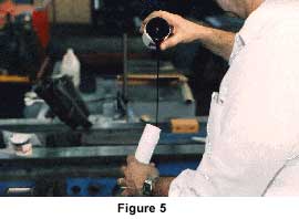
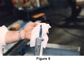
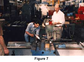
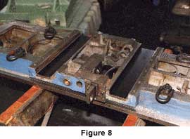
In figure 5 the fluid material has been mixed in its own container and is poured into an injection tube. The tube is put in a caulking gun and air is removed, as a doctor would remove air from a syringe (figure 6). The material is then injected into a void between the properly aligned saddle and the ground bed ways (figure 7). The void is sealed with lengths of "0" ring material. Approximately twenty hours later the saddle is detached revealing replicated ways (figure 8). In both applications, the saddles were aligned before the Moglice was applied. This eliminates the need to machine or scrape the Moglice.
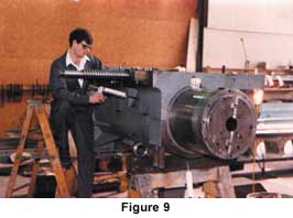
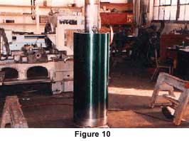
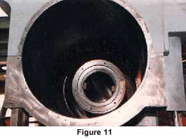
In figure 9 Moglice is being used to produce a new quill bore inside this Ingersoll horizontal boring machine headstock. The quill has been ground undersize .125" on diameter to provide .062" clearance between the quill and bore to be filled with Moglice and to make the quill an accurate surface to replicate from (figure 10). The quill is then coated with release agent, aligned in the bore and the Moglice is injected with a caulking gun. After approximately twenty hours cure time, the quill is removed revealing a finished quill bore, perfectly fit to the quill (figure 11). This is considered a repair rather than a rebuild because the quill is no longer original equipment size. The replication process can be completed without removing the headstock from the column, without having to bore, fit a sleeve and accurately re-bore a 22" diameter hole 36" deep into the large 7 ton casting. The replication process reduces down-time and cost and should be considered as a viable option.
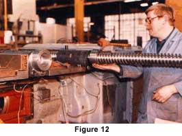
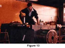
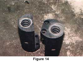
The elevating nuts for the headstock were also injected with Moglice. The old babbitt was melted out of the steel nut bodies. The lead screws were milled to provide an accurate lead and aligned on the headstock through the nuts (figure 12). The Moglice was then injected and allowed to cure (figure 13). The next day the screws were removed from the nuts revealing finished Moglice threads inside the nut, as seen in figure 14. This saves either the making of new nuts or the buying of new screw and nut assemblies. The replication material will faithfully reproduce any thread geometry. It does not matter whether the screw is metric or standard, fine-pitch or multi start high helix, the molding technique makes it easy to fit the nut. Being able to reuse the old nut body is especially economical when the body is difficult to machine or the delivery time for a new one is too long, as is often the case with expensive bronze nuts.
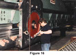
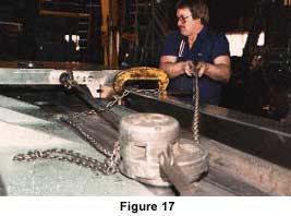
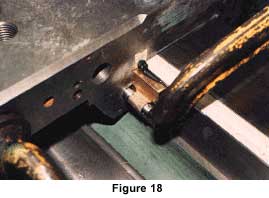
Static replication techniques were recently employed by Dorries to precision fit new column segments for what was a large Mesta vertical boring machine. This machine, located in the Voith Hydro facility, York, PA has been completely remanufactured by Voith's sister company, Dorries. The base, table and cross rail were the only parts retained. The remanufacturing included table bearing and drive improvements that left the old adjustable rail columns inadequate. Dorries produced new, more rigid segmented columns allowing the rail height to be adjusted by deleting or adding segments. These segments were mated to one another and to the cross rail at Voith Hydro with DWH 310, a static replication material. The saddles were mated to the rail and the rams mated to the saddles with Moglice low-friction replication material. As pictured in figure 15, there is about nine feet under the tool. With all four segments in each column, there is 19.1 feet under the tool. The table is 43.3 feet in diameter and has a capacity of 385 U.S. tons. The machine is reported to be the largest vertical turning center on the East Coast. Dorries has been building large machines with DWH and Moglice replication materials since 1976. Scharmann, Froriep, Wohlenberg, Heyligenstaedt and Hueller Hille are some of the other West German builders that have a long history with Moglice and DWH replication materials. In 1986 Voith Hydro also rebuilt a large Farrel vertical boring mill. The saddles and rams for the Farrel were mated with Moglice. In figure 16 the saddle is mated to the rail with the injection method and in figure 17 a main bearing gib is being molded with putty. The putty has been applied to the face of the gib. The gib has been put against the rail and the finished saddle is pulled over the gib to the full adjustment position (figure 18). The "C" clamp keeps the gib from sliding away and the uncured Moglice putty has enough constitution to press the gib flat against its back. This results in the correct taper and thickness of material being molded on the gib.
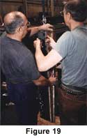
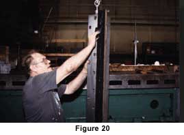
There are several other methods of applying replication materials to tapered gibs. One of the most effective methods is to screw the gib flat against its back in its full adjustment position (figure 19) and to Moglice it as if it were a standard way or retainer strap (figure 20). This method is particularly effective in applications like Ingersoll headstocks which often have 20 or more gibs and no positive sides.
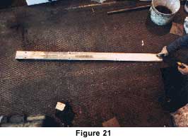
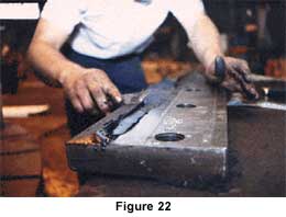
Refitting all these gib heads can be a problem even for the best scraping hands. Replication techniques end long hours of hand fitting by temporarily fastening the gibs flat against their backs on the head at their full adjustment positions. The head is then aligned correctly and the replication material applied. After cure, the gibs are removed and trimmed as finished gibs. At final assembly, all gibs are inserted to full adjustment and this automatically aligns the headstock on full bearing gibs. A third method for fitting gibs is to super glue small pre-cured pieces of Moglice to the adhesion surface on the face of the gibs (figure 21). The gib is then slid into position and the pieces of Moglice are checked for contact (figure 22). The ones making contact are filed or scraped until all of the pieces make contact and are forcing the gib flat against its back at or near full adjustment. The gib can then be molded against any flat surface because the pieces of Moglice provide for the correct thickness and taper. After curing, the pieces just become part of the bearing surface. Gibs done with this technique will usually require a few scrape cuts for proper bearing.
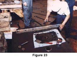
Straps or retainer ways are one of the easiest replication applications. In figure 23 Moglice putty is being troweled onto the adhesion surface of a strap. In figure 24 the Moglice is being spread out evenly with a putty knife. The strap is then bolted in position; the excess will squeeze out and the remainder molds a perfect line-to-line bearing surface. In almost all applications some clearance is desirable and can be provided for by one or two light scrape cuts.
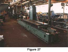
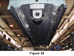
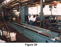
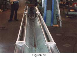
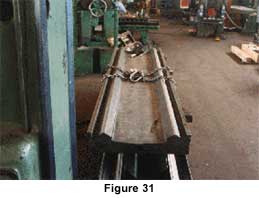
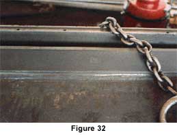
The Hillyer Machining Center shown in figure 25 had been designed and was running on roller packs. The machine is used for milling stainless steel billets at Gulfstream Aerospace. During the machining operation two 3,000 Ib. billets have approximately 80% of their stock removed. High stock removal rates required to machine these parts in a time effective manner took a toll on the roller packs and frequent realignment and replacement of roller packs was necessary. In an effort to decrease down-time and improve the surface finish of the parts, Gulfstream agreed to replacement of the rollers with plain Moglice slideways. The roller packs and adjusting wedges between the head slide and saddle, and between the saddle and cross rail were removed and replaced with solid full length filler bars Moglice was then used to align and mate the head to the saddle, and saddle to the cross rail. The alignments achieved with Moglice had to be correct because there was no longer a method to easily adjust them. The advantage is that the machine alignment will not be affected by machine vibration or crashes, eliminating the need for frequent adjustments. The full width of the available guide way was used, increasing surface contact, reducing vibration and further increasing slide stiffness. Gibs were then designed and produced to pull the Moglice plain slides against their guide ways . There was concern that the higher coefficient-of-friction of the plain slides would cause drive or positioning problems. An amperage draw reading was taken off the saddle drive motor while the saddle was still on roller packs. The amperage reading was repeated with the Moglice slide ways showing approximately a 10% increase in amperage draw. This machine has operated for over a year, twenty-four hours a day without requiring even a gib adjustment. The surface finish on the parts has been visibly improved. In other applications Moglice has been used in conjunction with roller packs. For instance, Moglice can be used to easily produce close fitting surfaces between the slide and guide way leaving clearance for only a thin layer of oil, which tends to dampen vibrations. A static replication material can be used to fit roller packs into perfect alignment and bearing in their pre-load state; or seats for roller packs can be replicated onto a slide by using a master fixture (figure 26). Replication techniques also lend themselves to the repair or rebuilding of hydrostatic bearing surfaces. Hydrostatic pressure pockets and return ports can be molded in, by using carefully placed magnetic or wax strips. The nature of the replication process makes it easy to produce consistent oil film clearances, even in the field.* *For a more complete discussion on replicated hydrostatic bearings see "Replication Materials in New Machine Architecture" by Andrew J. Devitt. Copyright SME 1990 presented at Session 10A, Sept. 11 IMTS 1990. The Pour and Set Technique The pour and set replication technique uses fluid material, but like putty, requires no sealing or injection ports. Because large quantities of fluid material can be mixed at one time, this technique is preferred for very large machine parts. Large planer tables, grinder tables and bed ways for vertical boring machines are excellent candidates for the pour and set method. The Rockford planer pictured in figure 27 has had its bed ways re-machined and leveled. The table has had small Moglice pads super glued to its way surfaces (figure 28). The table is set onto the bed ways and an alignment is taken. The Moglice pads are adjusted to achieve the correct alignment of the table. Machines with racks can have the gear backlash checked the full length of the rack on the Moglice pads. It is much easier to adjust the pads than to adjust the rack. With the pads correctly aligned, the table is roughened and cleaned for adhesion. The bed ways have been treated with a release agent and dams have been placed at the ends of the molding areas. The Moglice is mixed all at one time and poured evenly into the bed ways (figure 29). Note that the Moglice is almost self leveling (figure 30). The table is then set in the Moglice and the alignment is verified. After approximately 20 hours cure, the table is detached from the bed ways revealing table ways that are a perfect match to the bed ways (figure 31). In figure 32 a Moglice pad is just barely visible in the Moglice way surface. After trimming, spotting for oil retention and oil grooving, the slide is finished. This procedure has eliminated the need to match machine, the table ways and the trouble of scraping double vee ways for proper bearing.
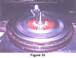
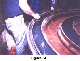
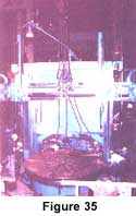
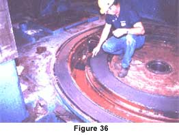
VBM Bedways Molded from the Table On long grinders and planers it is preferable and certainly more practical to apply the Moglice to the bottom of the table rather than apply the Moglice to the bed ways. On rotary tables though, the Moglice can be adhered to the bed way or the table ways. This option is especially useful since it is almost always easier to machine the table then it is to machine the bed. The accurately machined table can be used as a master to mold new bed ways with Moglice. As an example, the table for a 12' King vertical boring mill shown in figure 33 has been machined accurately and will be used as the master to replicate the new bed ways. Moglice has been mixed and poured into the bed ways; it is then spread out evenly with trowels (figure 34). The table is then set into the Moglice so that it comes to rest in its correct alignment (figure 35). Approximately 20 hours later the Moglice has cured and the table is removed. The excess material is trimmed off and the bearing surface is then flaked for oil retention and oil grooved resulting in finished low- friction bedways (figure 36).
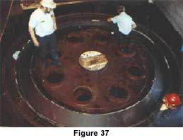
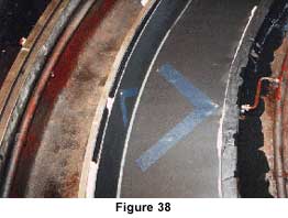
Oil grooves can be molded directly into the Moglice by positioning wax strip on the bottom of the table. This technique can be seen in figure 37 and figure 38 where the same pour and set method was used to produce new bed ways for an 18' Froriep vertical boring machine. After curing the wax is peeled out of the Moglice, leaving finished oil grooves. Notice that the bearing consists of two tapered surfaces making what is basically a round vee way. Vee ways, flat ways and round ways all lend themselves to the pour and set technique.
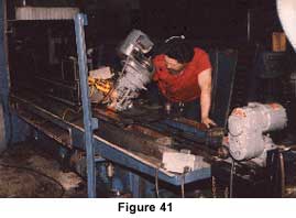
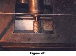
Portable Machining Replication techniques can be used to produce new bed ways when the mating table covers the entire bed way as in the rotary applications mentioned above. Replication techniques are not a practical method of requalifying large linear guide ways. For this reason Devitt Machinery Co. has been developing and promoting portable machining techniques for metal cutting machine tools. Portable machining is a method of requalifying the bed way surfaces of large planer mills, planers, grinders and lathes by guiding a temporary milling carriage on accurate clearance surfaces of the bed, or on temporary guide ways. After machining, tables, saddles or tailstocks can be fit to the fresh bed ways with replication techniques. Portable machining is not new but replication techniques make portable machining more practical for two main reasons. First, replication makes it easy to fit temporary milling carriages to accurate clearance surfaces that exist on the machine base. Second, after machining, replication materials can be used to fit the mating components to the fresh bed ways quickly. The examples that follow will illustrate these points. At Beloit Corporation, Beloit, Wisconsin, a large Ingersoll planer mill was machined in-place by Wisconsin Industrial Machine Service of Waukesha, Wisconsin in 1982 (figure 39). The bed ways on this machine are 14" wide x 112' long. The table liners are 12" wide x 56' long. Consequently a 2" wide area existed on each Bed way that was unworn and in its original condition. The unworn areas of the Bed ways were used as a datum line and with the use of a laser, these surfaces were leveled to .002" over the entire bed. Temporary bearing blocks of uniform heights were made and bolted and doweled to the bottom of the table (figure 40). All wear surfaces of the temporary bearing blocks were coated with Moglice moldable bearing material. The temporary bearing blocks also contain oil holes and tubing to permit lubrication during the machining operation. The worm drive of the machine was engaged with the table rack to provide table travel. Several trial passes were made with the laser target on the table to ascertain that the table travel was straight and level. The portable milling head was mounted on the table and the bed ways were successful machined. It was necessary to machine from both ends of the table to completely machine the bed. There was some concern that the cuts would not match perfectly. This proved not to be the case. No scraping was required. It was decided that Beloit Corporation would use Moglice for the table liners and that it would be cast in-place with no machining required. The table ways were scarified and cleaned to provide a suitable surface for the adhesion of the Moglice. The area of the table to be Mogliced was dammed to prevent leakage of the Moglice. A parting agent was applied to the bed to prevent the Moglice from adhering. The table was then placed on the bed resting on precision blocks which provided a cavity of .080". The oil system was redesigned to lubricate through the table rather than the bed. Moglice was injected through these oil holes to completely fill the cavity between the bed and table resulting in a finished table bearing. At Pratt & Whitney Machine Tool Corp., West Hartford, Connecticut, portable machine techniques were demonstrated by Devitt Machinery Co. on a 30 foot bed Hill Acme grinder. In this case, accurate clearance surfaces existed on either side of both ways. The bed was leveled to these surfaces and a simple plate was fit to these surfaces using replication techniques. A Bridgeport milling head was mounted to the plate and a variable speed Reeves drive, a reduction unit and a number 50 chain was used to pull the plate and milling head the length of the bed ways (figure 41 and figure 42). After machining the bed ways the table was fit to bed with Moglice using the pour and set application method discussed earlier. Richard Burkhart, President of Pratt & Whitney Machine Tool Corp., verifies the whole job was completed in less than 5 days and the machine has been running two shifts per day for over a year since the time of this writing.
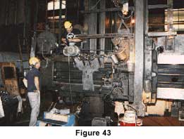
In many cases only one guide surface on a rail or a bed will be worn or damaged by scoring. In these cases the other bearing surfaces can be used as a guide to machine the worn ways. In figure 43 and figure 44 the back top guide surface of a vertical boring machine rail is being milled parallel with the face of the rail. Another common example would be the milling of cast iron tailstock guides for large lathes from hardened carriage ways. The possibilities of portable machining are limited only by your imagination and mechanical ability in combining elements to get the job done.
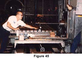
There are hundreds of other machines that are potential portable machining Candidates: many 100' plus shaft lathes in the shipyards up and down both coasts of America; many 20' plus vertical boring mills in the steel mills across the county; and, many 100' plus planer mills in the heavy equipment builders' facilities across America. There are literally hundreds of these machines with worn out bed ways. There are few rebuilders that can properly handle these machines in their shops. The conventional methods for rebuilding these machines (i.e. the removing of the bed castings from their foundations and shipping them to someone with the capability to machine them and the floor space to set them up and refit the components) is a costly and time consuming process. If the owner of the machine goes to this trouble he is likely to rebuild or remanufacture the entire machine. But the owner must also consider cost and lost production time while the machine is down. He must be able to justify a large investment in an old machine that will still have low resale value even after a complete overhaul. For these reasons many large machines continue in use unimproved. The owners of these machines are not aware nor are the rebuilders aware that the bed ways of these machines can almost always be machined in-place and the large components can be refit to the new bed surface with replication techniques quickly and economically in-place. The knowledge of this process dramatically changes the way the owners of these large pieces of equipment look at the rebuilding process. In many cases these owners do not want a complete rebuild. They would just like to have their machines cut accurately again. That is, they would like to have their machine requalified. This process "portable machining and replication" eliminates the need to remove bed castings or machine the mating components and dramatically reduces the time the machine will be out of service. Few rebuilders see the merit of this process yet, but it actually increases the size of their potential market. When they cannot sell a complete rebuild for 1 million dollars they may well be able to sell a requalification for 1/4 million dollars. The smaller pieces of the machines such as headstocks, saddles and rams could be taken back to the rebuilder's shop and the main bed castings could be requalified in-place with portable machining techniques. Few rebuilders are offering this service. Few large equipment users are aware of this process but, this process has the potential to revolutionize the way large equipment users look at improving their equipment. Even the largest planer mills can be machined in-place in one to three weeks time. It does not matter whether the machine has flat ways, vee ways or Ingersoll type tubular ways. In fact, Ingersoll half round bed ways are one of the easiest types to portable machine and because the table ways are replicated from the bed ways, there is no reason to remove the tubular ways from the table. This is a clear example of how these techniques broaden the number of rebuilders that can complete large work. If these techniques were employed more broadly, it would add to the capability and accuracy of American's large equipment base and create more work for U.S. machinery rebuilders. Requalification of beds and slides is the first step toward more advance remanufacturing. Large seasoned cast iron machine structures make stable rigid platforms for remanufacturing projects. The custom engineering necessary when remanufacturing an older machine to satisfy an updated purpose, again broadens the market for machine tool rebuilders. Cooperation with heavy machine tool builders or rebuilders, as was the case at Voith Hydro, is a practical way to approach a large remanufacturing project. A machine does not have to be large to be a good candidate for replication techniques. Many CNC machine tools in the last 10-15 years have been built with some type of sheet-type low-friction slide way material. When this sheet-type material wears out or unbonds, it can be replaced in the field with a replication material quickly. As an illustration between common practices and replication techniques, consider the DeVIieg table shown in figure 45. Following the replication process this table is aligned on 1" square .060" thick shims of pre-cured Moglice which are super glued to the adhesion surfaces of the flat ways. These shims are adjusted by scraping or filing until "0" readings are achieved across the top of the table. Two shims are used on one side of one of the two vee ways to achieve table squareness. It is not necessary to turn the table to adjust any of these shims.
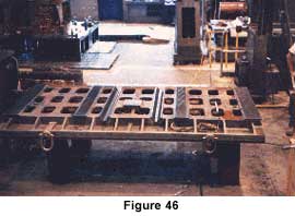
Once the alignment is correct Moglice putty is troweled onto the adhesion surfaces. The table is then set in place on the saddle and alignments are verified. The next day the table is removed from the saddle and excess Moglice is trimmed off (figure 46). The surfaces are flaked to break up the bearing and provide oil retention and oil grooves are cut. By the end of the second day the table is set back on the saddle to verify the correct bearing contact and alignment of the finished ways.
Using common techniques, sheet-type materials would be glued onto the adhesion surfaces on the first day. On the second day the ways would be lightly milled if a machine were available to do the same. It would then require an additional 3-5 days to scrape the ways into correct alignment and bearing contact. This scraping procedure requires great skill and patience to scrape double vee ways for squareness in congruence with four other flat ways. It is simply easier to achieve an alignment first and apply a replicating material than it is to apply a sheet-type material and machine and scrape for alignment later. The DeVIieg Field Service Coordinator, Dave Parker, testified to this in a June 16, 1987 letter stating "we have been using Moglice material for about 2-1/2 years now...and have found that on some of our repair/rebuild jobs the use of Moglice has saved as much as 75% of the down-time that would have been needed to apply sheet-type way material". Common Bearing Materials MOGLICE
|
||||